

Driver-free by design,
not by compromise.
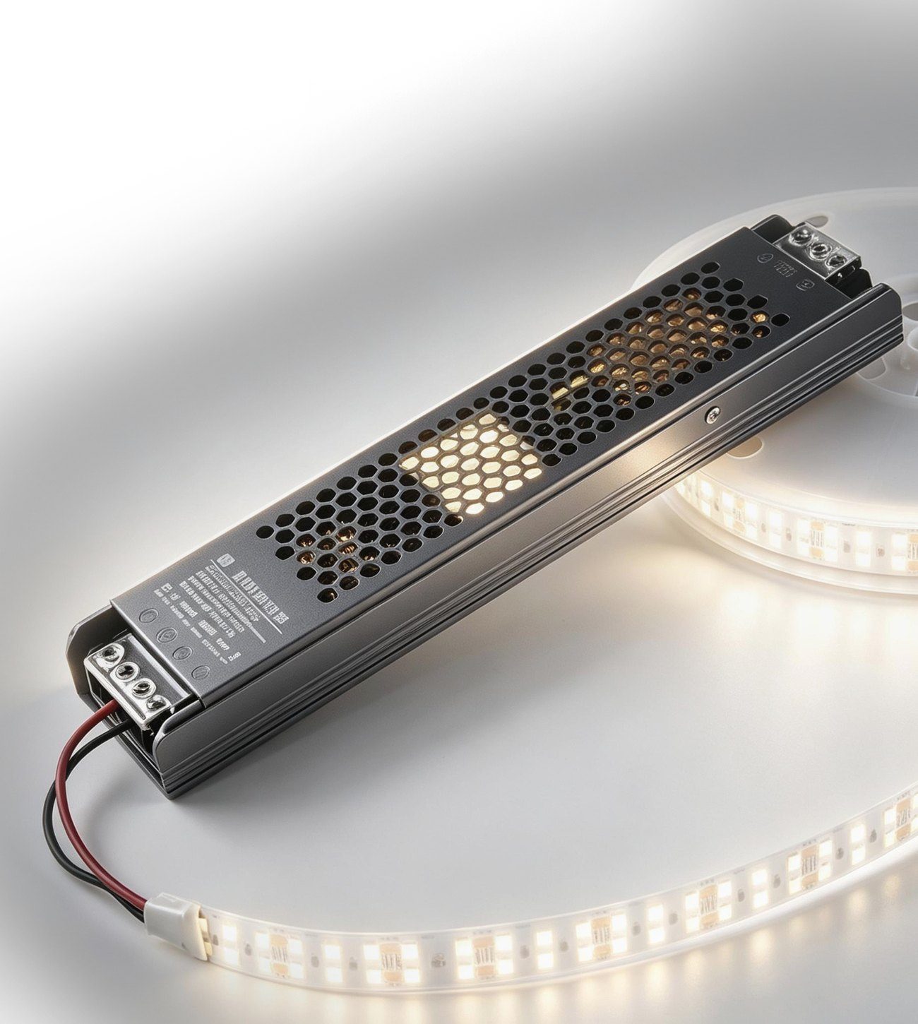
We replace the switching power supply with a linear constant-current chip that lives on the light source board itself. The result is a shorter circuit, fewer failure points and light quality that resistor-based packaging cannot reach.
A structural problem, not a component problem.
As current-driven devices, LED chips require precise constant-current driving to deliver optimal performance. Conventional solutions rely on external switching power supplies, which raise BOM cost and assembly complexity - and stand as the leading cause of failures in LED luminaires.
-
Complicated assembly
Extra PCB, connectors, mains wiring and an additional production step for every luminaire.
-
High installation cost
Distributed wiring brings numerous complex connectors, low construction efficiency and difficult maintenance.
-
Increased maintenance risk
Electrolytic capacitors and cold solder joints are the first things to age and the hardest to service.
-
Efficiency losses
Switching loss and long wiring paths turn electricity into heat that warms the LED in reverse and accelerates light decay.
AC power straight into the chip.
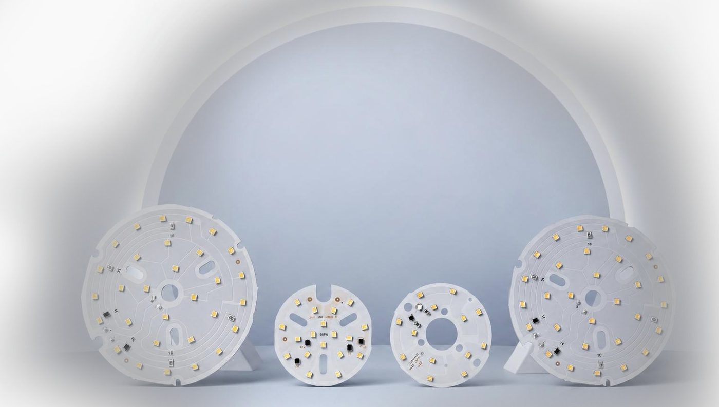
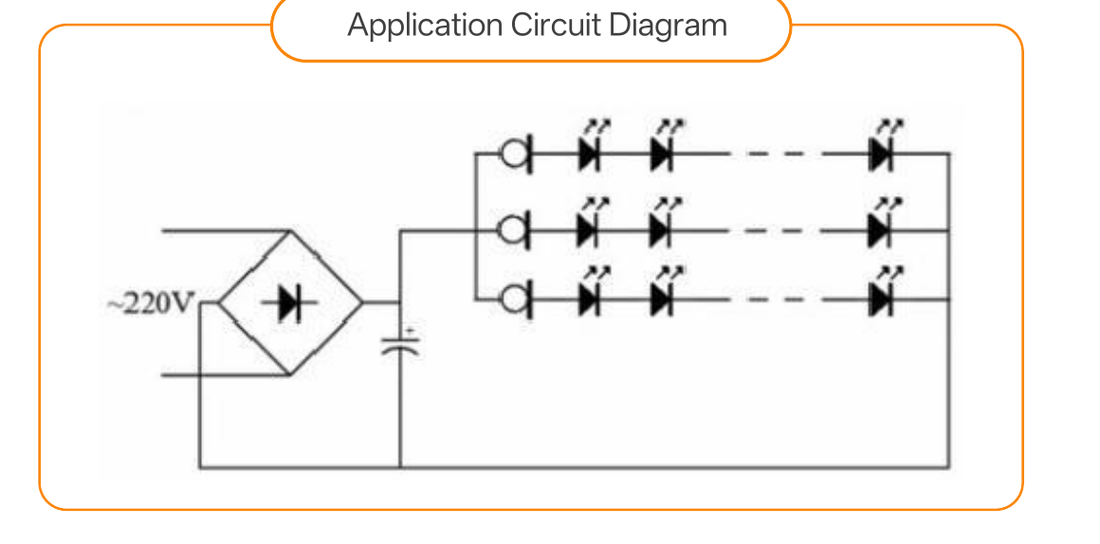
Lumichips offers a completely differentiated solution: we integrate the entire driving circuit into a single CRD constant-current chip, which can be directly mounted on the light source board. AC power is fed straight into the chip without any external driving components.
This chip maintains highly stable current across a wide voltage range from 3 V to 220 V. Equipped with built-in surge protection, it can withstand the harshest power grid conditions worldwide.
One chip is a complete driving solution.
The Lumichips CRD series constant-current driver chips are linear driver solutions specially designed for LED lighting. Unlike traditional external driver power supplies, CRD chips can be directly mounted on LED light source boards to deliver high-precision constant-current driving with an ultra-minimal circuit.
No inductors, transformers or electrolytic capacitors are needed. One single chip constitutes a complete driving solution.
| # | Value point | Technical specification | Customer benefits |
|---|---|---|---|
| 1 | Driver-Free | No external driver power supply required; AC input connects directly to the chip. | Cost-saving · Space-saving · Labour-saving · Halved failure points |
| 2 | High-Precision Constant Current | Highly accurate current output (actual test data) with stable constant-current output. | Flicker-free · Stable colour temperature · Maximises LED chip service life |
| 3 | Wide Voltage Adaptability | Low startup voltage down to 3 V, full coverage up to 220 V. | Compatible with power grids worldwide; no component replacement required. |
| 4 | Surge Resistance Protection | Built-in surge protection, expandable up to 10,000 V. | No damage during thunderstorms; rock-solid stability in industrial environments. |
Integrated driver IC vs. resistor light source packaging.
The same luminaire, two architectures. Every row below is a decision point that shows up in the field as flicker, colour shift, heat or call-outs.
| Comparison dimension | Integrated packaging of driver IC | Resistor light source packaging |
|---|---|---|
| Current stability | Built-in IC closed-loop control delivers absolutely constant current. | Current fluctuates drastically with input voltage and temperature variations. |
| Input voltage adaptability | Wide voltage range. Typically supports 6 V-24 V or even wider, with fully unchanged brightness. | Extremely narrow range. Must strictly match rated voltage; slight overvoltage easily causes burnout, while slight undervoltage leads to dim light. |
| Light uniformity batch / series & parallel |
Excellent. The IC sets precise current, unaffected by VF dispersion of LED chips. | Very poor. When connected in parallel, beads with lower VF hog current (overbright or burnt out), while beads with higher VF stay dim. |
| Thermal management & safety | Intelligent design. Built-in Over-Temperature Protection (OTP) automatically reduces current at excessive temperature to prevent burnout. | No protective mechanism. VF drops under high temperature, triggering sharp current surge (thermal runaway) and high risk of burnout. |
| System efficiency & heat generation | High efficiency. Controllable IC voltage drop results in minimal reactive heat loss. | Low efficiency. Resistors bear all excess voltage, generating pure heat loss. |
| Peripheral circuit complexity | Extremely simple. Usually only power supply connection required, no external drivers or resistors needed. | Resistors mandatory. Current-limiting resistors must be calculated and connected in series for each circuit loop. |
| Single light source cost | Relatively high. Built-in IC increases packaging cost. | Extremely low. Conventional, mature and low-cost structure. |
| Overall BOM & assembly cost | Potentially lower. Eliminates external driver power supplies and resistors for ultra-simple production and assembly. | Potentially higher. Requires external power supplies and resistors, increasing labour hours for assembly and maintenance. |
Source: Lumichips brand manual, technical advantage comparison.
What changes beyond the current waveform.
Luminous efficiency, service life, light quality, dimming, integration, EMI and total installed cost.
| Comparison dimension | Integrated packaging of driver IC | Resistor light source packaging |
|---|---|---|
| Luminous efficiency | Extremely high and stable. Chip-level constant current control keeps LEDs running at their optimal operating points. High conversion efficiency generates minimal waste heat and low heat-induced light decay. | Restricted by losses of discrete components. Resistors generate Joule heat and dissipate energy directly; long wiring paths bring non-negligible circuit losses. Heat emitted by resistors warms LEDs in reverse and accelerates light decay. |
| Service life | Dramatically improved reliability by orders of magnitude. Eliminates resistors and solder joints to completely eradicate failure modes such as cold solder joints and thermal fatigue. The IC and LED are co-packaged in the same thermal field with highly consistent aging rates; a fully solid-state lamp interior with no electrolytic capacitors approaches the same service life as the light chip. | Dual hidden risks from solder joints and parameter drift. Two independent solder joints on each resistor act as weak points. Resistance value drifts with temperature and humidity, triggering current runaway and local overload. |
| Light quality | Professional health-grade lighting. True flicker-free performance, high colour rendering, and consistent accurate colour temperature across all brightness levels. | General lighting grade. Flicker level close to the safety threshold, low grayscale with colour shift, limited light uniformity. |
| Dimming performance | Deep stepless dimming. The integrated IC supports high-precision digital / analog dimming. Dimming depth reaches 0.1% with no stepped flicker throughout the range. | Limited dimming range. Resistor current limiting only supports fixed gears or narrow-range PWM dimming. Grayscale jump and flicker easily occur at low brightness. |
| Integration & size | High integration and ultra-thin design. No space occupied by peripheral resistors for slim, compact modules. Easy to develop flexible light strips with high pixel density. | Large PCB footprint. Extra space required for current-limiting resistors and pads for each LED channel. Restricts miniaturisation and dense layout design of lamps. |
| Electromagnetic compatibility (EMI) | Low interference at the source. Proximal constant-current drive forms an extremely small high-frequency loop. Ultra-low electromagnetic radiation with no extra filtering components required. | Potential EMI risks. Parasitic inductance of long wires and PWM chopping easily cause ringing noise. Extra filtering components may be required to suppress interference. |
| Cost & installation | Greatly reduced system cost and extremely simplified construction. Eliminates the hassle of distributed "one driver per lamp". Lamps are connected to the bus in parallel with fewer connectors and fault points, lowering construction technical barriers and improving construction safety. | Deceptively low component cost and cumbersome installation. Single resistors cost little yet large quantities are needed, leading to higher total material and labour costs. Each LED bead requires separate resistor soldering, doubling solder joints and hidden faults. Distributed wiring brings numerous complex connectors, low construction efficiency and difficult later maintenance. |
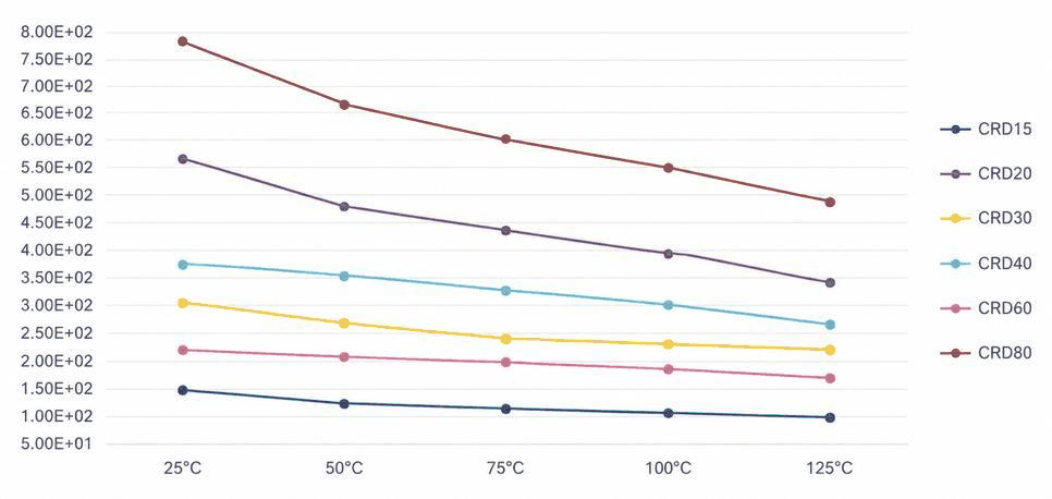
Measured behaviour, not marketing curves.
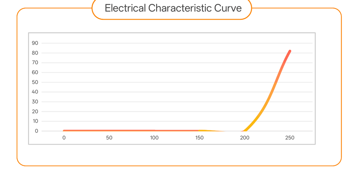
The CRD holds a flat current plateau across the operating voltage window before the shoulder, and drift stays bounded across the full temperature range.

Evaluate the CRD in your own luminaire platform.
We share reference schematics, thermal guidance and sample chips for bench evaluation.